We use cookies to make your experience better. To comply with the new e-Privacy directive, we need to ask for your consent to set the cookies. Learn more.
Wiring instructions for single phase regulator/rectifier (Our reference number 100415)
- Disconnect the ground wire from your battery. Check if your system is positive or negative ground.
- Locate and remove the Zener diode pack as you will no longer need it (its gold coloured)
- Locate and remove the selenium rectifier. You no longer need this either.
- There should be 3 wires connected to the rectifier. The green/white and green/yellow go to the alternator stator. The hot wire is usually brown/white/ This goes to the hot side of the battery.
- Connect these two wires to the 2 yellow wires on the rectifier/regulator.
- Mount the power module in an area of free air circulation. Please note the heat sink is electrically isolated and does not have to be grounded.
- If your system is positive earth, connect the red wire to ground and the black wire to output.
- If your system is negative earth, connect the black wire to ground and the red wire to output.
- Double check all the connections are correct and reconnect the ground wire to the battery.
Wiring instructions for three phase regulator/rectifier (Our reference number 100419)
- All wiring instructions are as the same as the single phase apart from the following;
- The should be 4 wires connected to the rectifier. The white/green, green/black and green/yellow connect from the stator to the rectifier.
- Connect the 3 stator wires to the 3 yellow wires on the power module.
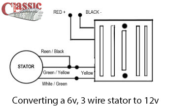
Converting a 6v, 3 wire stator to 12v
If you have a 6v, 3 wire stator you can convert it to the 12v by connecting the green/black and green/yellow wires together then connecting those two to one of the yellow AC wires and then connect the green/white wire from the stator to the other yellow AC wire of your power module.
Then the red + and the black _ connect into your motorcycle wiring.
Remember to change your bulbs, battery, horn ect to 12v too! Please see the diagram illustrated below...


